Raspberry Pi Serial Port Uart Interface
The Universal Asynchronous Receiver/Transmitter (UART) takes bytes of data and transmits the The Raspberry Pi actually has two UARTs. One UART is part of the internal ARM architecture of A serial port is a sequential statement physical interface throughout which detail transfers inside. Raspberry Pi Resources. Our resources for other geeks, designers and engineers. Update from Maurice Garcia in the comments – If you are using PI model 3 do not use /dev/ttyAMA0 this ERROR - CAN'T OPEN SERIAL PORT printf('Error - Unable to open UART. Ensure it is not in use by another.
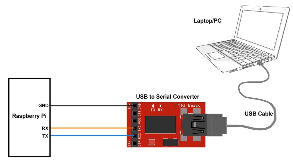
In this tutorial we will see how to use the serial port on. We will use the serial port available on Raspberry with a and a. By default the Raspberry Pi’s serial port is configured to be used for console input/output.
This can help to fix problems during boot, or to log in to the Pi if the video and network are not available. To be able to use the serial port to connect and talk to other devices (e.g. A modem a printer. ), the serial port console login needs to be disabled. Here we use Raspberry Pi 2, and we connect a RS232/TTL 3-5,5V adapter to pins 4 (5V), 6 (GND),8 (TX),10 (RX) of Raspberry, obviously connect tx with rx and vice versa.
This post is on interfacing GSM with Raspberry PI 3 B or B+. UART is commonly used on the Pi as a convenient way to control it over the GPIO, or access the kernel boot messages from the serial console (enabled by default). It can also be used as a way to interface GSM / GPS /Arduino / ESP8266, etc with your Pi. Be careful with logic-levels between the devices, for example the Pi is 3.3v and the GSM is 5v. In the previous versions of PI GPIO Serial port is mapped to /dev/ttyAMA0 (COM1 equivalent is found on pins 14 and 15 of the GPIO header and is called /dev/ttyAMA0 ) But in PI 3 B or B+ this hardware port has been utilized for the BLUETOOTH Functionality. /dev/ttyAMA0 is a hardware, high performance serial port (uart) & used for the Bluetooth A second port is partly software /dev/ttyS0 & is assigned to GPIO Serial port.

So, the ports on a Raspberry Pi 3 are ——————————————————– /dev/ttyAMA0 -> Bluetooth /dev/ttyS0 -> GPIO serial port (referred to as the “mini uart”). ————————————————– Thus on a Raspberry Pi 3 serial0 will point to GPIO pins 14 and 15 and use the “ mini-uart” ( /dev/ttyS0). On older Raspberry Pi’s it will point to the hardware UART and /dev/ttyAMA0. To start with write the OS on a class 10 memory card using ETCHER Use the SD card on RPI 3 & log in To know the Serial ports enabled, type in cd /dev & then ls –l You can see only the ttyAMA0 is enabled & not the mini uart ttyS0 The GPIO serial port is disabled by default. In order to enable it, edit config.txt: $ sudo nano /boot/config.txt and add the line (at the bottom): enable_uart=1 Reboot for the changes to take effect. Restart the Putty SSH Now check the cd /dev, ls –l again You can see both the ports enabled. Note that this can be done through raspi-config also.
Let us connect the GSM with PI now. The logic levels of PI are at 3.3 volts & it is risky to connect directly with a 5v level GSM pin. The Tx pin (pin 8, GPIO14) of PI can be directly connected to Rx of GSM. As GSM accepts 3.3volt level as high, this connection is straight without level shifting. However the Rx pin (pin 10, GPIO 15) of PI cannot be connected directly to Tx of GSM. A simple level shifter using a signal diode 1N4148 & a 10k resistor is used in between as shown below LOGIC LEVEL SHIFTER When the level at GSM Tx is LOW, the diode is forward biased & the Rx of PI gets LOW.
These events can remove your CAPs, activate an enemy unit or add Rumored Enemy units to the map. When the Mission Track token advances if it lands on an event it is immediately resolved. Rumored Enemy units are revealed when they take an action, move in open terrain or are fired at. Sometimes they are AI units and sometimes they are rumors. Archipelago solo expansion rules pdf.
When the level at GSM Tx is HIGH,the diode is Reverse biased & the 3.3v is available at Rx of PI through the resistor. A separate power source 12v 1 amp is required for GSM, and the GND pins of PI & GSM are made common. Be cautious while connecting with PI pins, as any wrong connection will render the PI defective. After powering the GSM wait for the network. The network LED blinks fast initially & after getting Network it blinks slowly.